Electric motors and generators rely on curved magnetic pieces that fit precisely into circular assemblies. A magnet segment does exactly that job, and specifying one correctly takes more care than most buyers expect. This guide explains what they are, how they are made, and what to check before ordering.
What Is a Magnet Segment
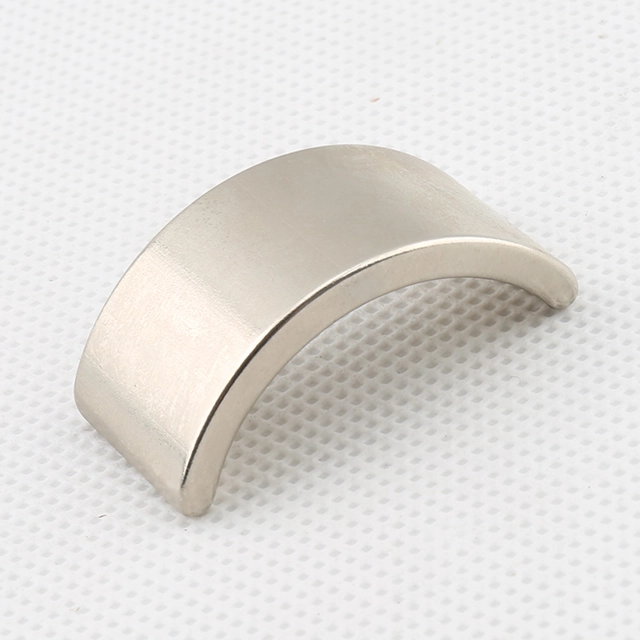
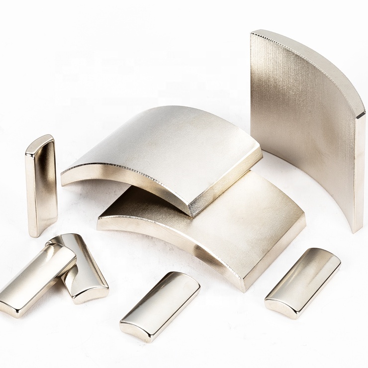
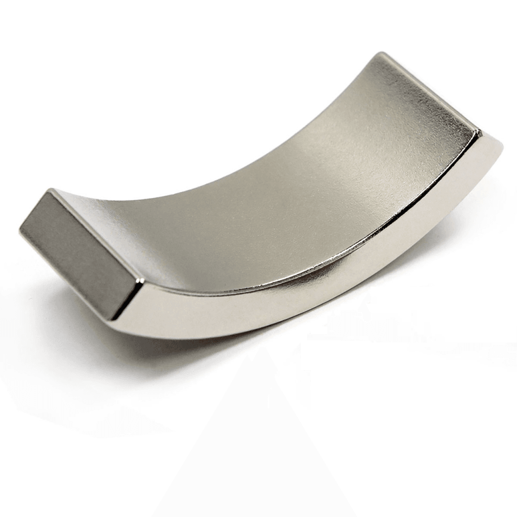
A magnet segment is a curved permanent magnet shaped like a slice of a ring. It has an inner radius, an outer radius, an arc angle, and a thickness. That curved geometry lets it sit flush against a cylindrical rotor or inside a stator housing.
Most magnet segments are made from neodymium-iron-boron, the strongest permanent magnet material available. Ferrite and samarium cobalt versions exist for cost-sensitive and high-temperature applications. The curved shape is not cosmetic. It keeps the air gap between the magnet and the opposing magnetic structure uniform all the way around the circumference, which is what allows a motor to run smoothly.
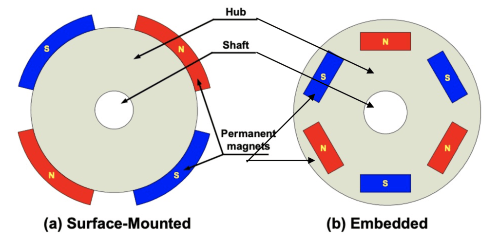
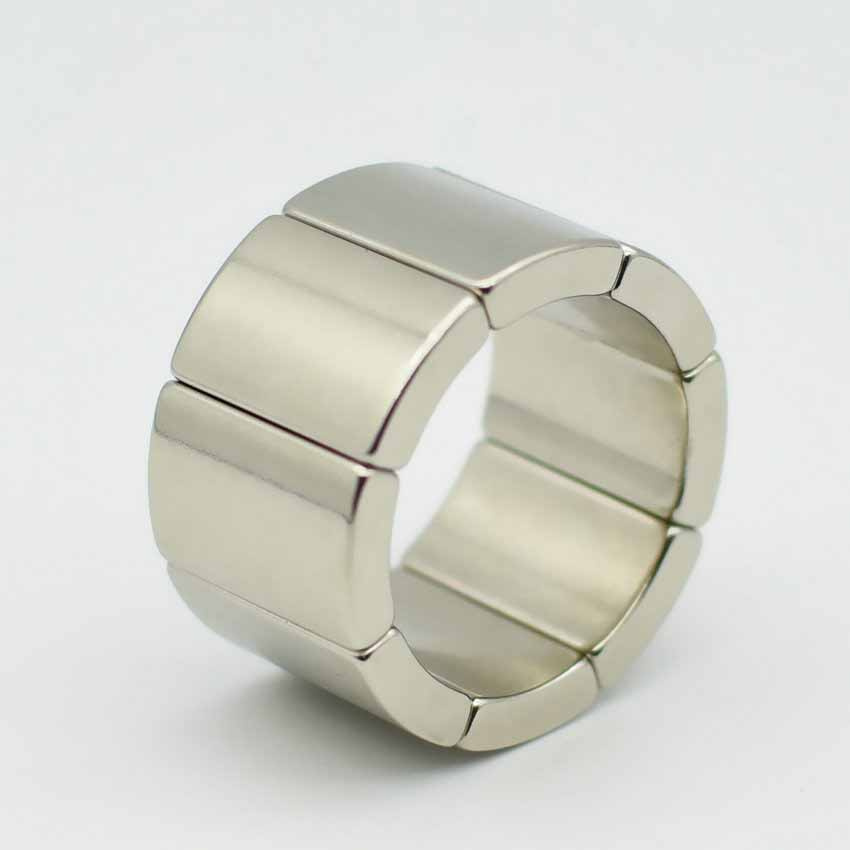
A single segment covers only part of a circle. Several segments arranged in a ring form the complete magnetic pole structure. An eight-pole motor, for example, might use eight segments of 45 degrees each, alternating north and south around the rotor.
Why the Curved Shape Matters?
Flat magnets can be used in motors, but they create problems. A flat magnet pressed against a curved rotor surface leaves gaps at the edges. Those gaps weaken the magnetic field and create uneven flux distribution. The result is vibration, noise, and reduced efficiency.
A magnet segment follows the rotor contour exactly. The air gap stays constant, so the flux density stays constant. That consistency translates into smooth torque output and quieter operation. In high-speed motors, even small variations in the air gap cause vibration that wears bearings prematurely.
The curved shape also improves mechanical retention. Segments can be bonded to the rotor surface or inserted into slots. The curve distributes centrifugal force more evenly than a flat piece would, which matters in motors spinning at thousands of revolutions per minute.
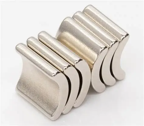
Magnetization Directions Used in Segments
Magnetization direction is the specification that causes the most ordering mistakes. There are three common patterns.
Radial magnetization is the most common for motor segments. The north pole sits on the outer curved face and the south pole on the inner curved face, or vice versa. Field lines run outward from the rotor center.
Parallel magnetization places the poles on the two flat end faces of the segment rather than the curved surfaces. This pattern is used in some sensor and coupling applications.
Multi-pole magnetization puts several alternating poles across a single segment. This is used in encoder rings and certain linear motor designs. The pole pitch must match the sensor or controller requirements exactly.
Always confirm the direction in writing and ask for a diagram. Suppliers sometimes default to radial magnetization when the customer intended something else. Once the segments are magnetized, the error cannot be corrected.
Manufacturing Process for Magnet Segments
Understanding how these parts are made helps you evaluate supplier capability.
Production starts with alloy powder. Neodymium, iron, and boron are melted together, cooled, crushed, and milled into fine powder with controlled particle size. A lubricant is added to help the powder flow during pressing.
Pressing forms the curved shape. The powder fills a die cavity with the exact arc geometry. Punches apply pressure from multiple directions to achieve uniform density, because density variation across a curved part causes distortion during sintering. The green compact holds the shape but is fragile.
Sintering bonds the particles. The parts travel through a controlled atmosphere furnace at roughly 1000 to 1100 degrees Celsius. Atomic diffusion welds the powder grains together. The part shrinks by about 15 to 20 percent, and the tooling is built oversized to compensate.
Grinding brings the segment to final dimensions. The inner and outer curved surfaces are ground to exact radii, and the end faces are ground to the precise arc angle. This step is where dimensional accuracy is won or lost. Even small errors in radius cause an uneven air gap.
Coating protects the magnet. Nickel plating suits clean indoor applications. Epoxy coatings handle moisture, oil, and outdoor exposure. Some electric vehicle motors use specialized coatings compatible with transmission fluid.
Magnetization is the final step. The finished segments pass through a magnetizing fixture that establishes the permanent field. The fixture design determines the pole pattern.
What to Check Before Ordering
Specifying a magnet segment correctly means covering several details, not just dimensions.
Confirm the grade and the temperature rating together. A grade like N42SH tells you both strength and thermal limit. For motors that run hot, the temperature suffix often matters more than pushing the grade number higher.
Check the coercivity value separately. Two segments with the same grade can resist demagnetization very differently depending on coercivity. Ask for demagnetization curves at your operating temperature.
Verify the dimensional tolerances. Critical dimensions are the inner radius, outer radius, thickness, and arc angle. Tight tolerances cost more, so specify them where they matter and relax them elsewhere.
Ask about concentricity. The inner and outer radii must share a common center. If they do not, the segment will not seat properly and the air gap will vary.
Review the coating thickness. Coating adds to the nominal dimensions. A segment specified at 5 millimeters thick may measure 5.2 millimeters after coating. If your rotor slot is tight, account for this.
Request samples before full production. Test them in your actual assembly and measure the air gap at several points around the circumference.
How Coating Selection Affects Magnet Segment Performance
Coatings are often treated as an afterthought when ordering a magnet segment, but they influence both durability and dimensional fit. Getting the coating right protects the magnet for years. Getting it wrong causes corrosion, assembly problems, or both.
Neodymium segments corrode quickly without protection. In humid air, oxidation begins within days. In contact with water, salt, or coolant, a bare segment can deteriorate within weeks, and the damage is permanent. This is why every neodymium magnet segment ships with a coating, and why the coating choice should be made deliberately rather than by default.
Nickel-copper-nickel plating is the standard option. It provides a bright silver finish and adequate protection for clean, dry environments. It is also the most economical choice. For motors running indoors in controlled conditions, nickel plating is usually sufficient, and it adds minimal thickness to the finished part.
Epoxy coating is the better choice when moisture, oil, or temperature swings are present. The thick polymer layer seals the segment completely and resists salt spray, coolant, and humidity. Electric vehicle traction motors often use epoxy-coated segments because the rotor environment includes hot transmission fluid and condensation. The trade-off is added thickness, typically 0.1 to 0.3 millimeters, which must be factored into the rotor slot dimensions.
Parylene coating serves medical and high-reliability applications. The vapor-deposited layer is pinhole-free and only microns thick, so it barely affects dimensions. It is biocompatible and chemically resistant, which makes it suitable for surgical motors and laboratory equipment.
Rubber and plastic coatings appear in lower-speed applications where grip or impact resistance matters. They add significant thickness, so they are rarely used in precision motor assemblies.
Before ordering, confirm the coating type, the thickness it adds, and whether the quoted dimensions are pre-coating or post-coating. This single clarification prevents a large share of fitment problems with magnet segments.
How Temperature Ratings Determine Magnet Segment Reliability
Temperature is the most common reason a magnet segment fails in service, and it is also the specification most often misunderstood. Getting the temperature rating right is not optional in motor design.
Neodymium segments lose strength as they heat up. Some of that loss is temporary and recovers when the magnet cools. Some of it is permanent. The line between the two depends on the magnet’s coercivity and how far past its rated limit it is pushed. A segment that briefly touches its maximum temperature will usually recover. A segment that sits above that temperature for hours will not.
This is why the letter suffix matters more than the grade number in many motor applications. An N42SH segment maintains its properties up to 150 degrees Celsius. An N42 without the suffix may begin losing strength above 80 degrees Celsius. Both are N42. Only one survives in a hot rotor.
Motor designers often measure the outside of the housing and assume that is the operating temperature. It is not. The magnets sit near the windings, where temperatures can run 30 to 50 degrees higher than the exterior. In a sealed motor, heat has nowhere to go. The internal temperature climbs steadily during continuous operation.
The practical approach is to measure or model the actual magnet temperature under worst-case load, then add a safety margin of at least 20 degrees. Specify the lowest temperature grade that covers that figure, because every step up in temperature rating adds dysprosium content and cost.
Also confirm that the supplier provides demagnetization curves at your operating temperature. A magnet segment rated for 150 degrees Celsius should still show meaningful coercivity at that temperature on the data sheet. If the supplier cannot provide that curve, they cannot guarantee the segment will hold its field in your motor.
Common Mistakes When Buying Magnet Segments
Most problems trace back to a short list of avoidable errors.
Ignoring the air gap tolerance is the most frequent. Buyers focus on the magnet’s magnetic strength and overlook dimensional precision. An uneven air gap destroys motor efficiency regardless of how strong the magnet is.
Specifying grade without checking coercivity comes second. A high-grade segment with low coercivity can demagnetize in a hot motor, and the failure is permanent.
Forgetting that coating adds thickness causes assembly problems. Segments that fit perfectly in a dry test may not fit once coated.
Ordering too few spares is a practical mistake. Segments are brittle and can chip during assembly. Having a few extra pieces on hand prevents a stalled production line.
Skipping the magnetization diagram leads to parts that cannot be used. Confirm the pole orientation visually before tooling is cut.
FAQ: Your Magnet Segment Questions Answered
1. How many magnet segments are needed for a motor?
It depends on the pole count. A motor with eight poles uses eight segments, each covering 45 degrees. A twelve-pole motor uses twelve segments of 30 degrees each. Higher pole counts produce more torque at lower speeds. The pole count is set by the motor’s electrical design, not by the magnet supplier.
2. Can magnet segments be used in generators as well as motors?
Yes. The same curved geometry works in generators, including direct-drive wind turbine generators. In a generator, the segments create the magnetic field that induces current in stationary coils as the rotor turns. The requirements are similar, though generator segments are often larger and need higher temperature ratings.
3. What causes magnet segments to crack during assembly?
Three things: impact, thermal shock, and stress concentration at sharp edges. Dropping a segment or letting it snap against a steel surface causes chipping. Rapid temperature changes create internal stress. Sharp corners concentrate stress during press fitting. Warm the rotor before bonding, handle segments gently, and use assembly fixtures that locate the part without impact.
Conclusion
A magnet segment is a precision component, not a commodity. The curved shape exists to maintain a uniform air gap, and every specification from radius tolerance to magnetization direction supports that goal. Get the grade, coercivity, dimensions, coating, and pole pattern right, and the motor will run smoothly for years. Get any one of them wrong, and you will be dealing with vibration, heat, and premature failure. Take the time to verify the details before tooling is cut, and confirm with samples before production begins.
How to Choose Magnets for Electric Motors Without Wasting Money?